Technological development related to decommissioning
(2019)
QWhat happened to the inside of the reactor pressure vessel and storage vessel after the accident?
AJAEA has obtained detailed analysis of valuable measurement data obtained from the Fukushima Daiichi Nuclear Power plant at the time of the accident, results of damage tests on simulated fuel assemblies, prediction of severe accident analysis code and the latest. By comparing with the results obtained from the internal investigation of, we analyzed and evaluated the accident progress behavior of each unit and estimated the situation inside the reactor after the accident.
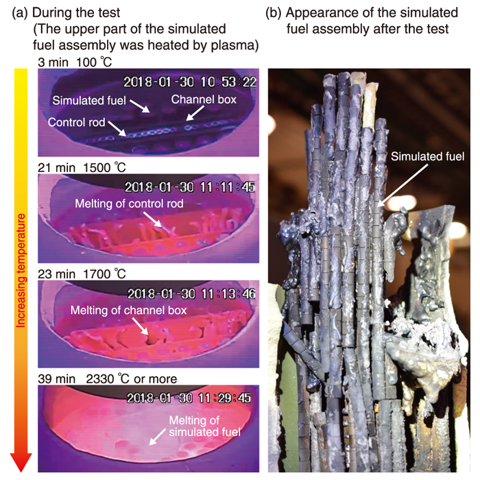
Fig.1 Core-material melting and relocation (CMMR) test
The simulated fuel assembly at the top was heated by plasma.
A ZrO2 pellet was used, rather than UO2.
(a) A downward flow was observed in order of materials with lower melting points.
(b) The simulated fuel retained the column shape until its melting temperature.
The decommissioning of the TEPCO’s Fukushima Daiichi NPS (1F) has been underway since its severe accident (SA) in March 2011. Estimating and comprehending the state of the remaining fuel debris and fission products inside the nuclear reactor is essential for this process. However, understanding the state the reactor pressure vessel (RPV) and primary containment vessel (PCV) is extremely difficult after an accident, as direct observation of the reactor interior is difficult due to the high radiation environment.
Additionally, as Unit 1 - Unit 3 at 1F lost their cooling functions during the tsunami, as well as their direct-current electric power supply, measurements cannot easily be collected from the onboard meters. Thus, information measured during the accident progression is in short supply.
To make up for this lack of accident information, SA models based on knowledge of the Three Mile Island (TMI-2) accident and some experimental work can be applied. However, core degradation in a boiling water reactor (BWR) like the 1F has not been comprehensively studied.
Since the TMI-2 accident, many researchers have focused on the initial core melting process and aspects related to the rupture of the pressure vessel in a pressurized water reactor (PWR). The differing structure between a BWR and a PWR may result in different core damage, melting, and slumping in the 1F accident.
In the “Upgrading of the comprehensive identification of conditions inside reactor” project, core-material melting and relocation (CMMR) tests were conducted to understand the collapsing, melting and relocation of core materials during 1F accident (Fig.1).
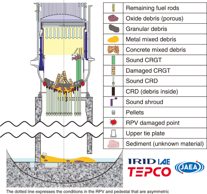
Fig.2 Estimated debris distribution and the RPV and PCV conditions in Unit 2
The state of residual fuel in the lower plenum were estimated via the results presented in Fig.1.
A fuel assembly simulating the core of a BWR using ZrO2 pellets rather than fuel pellets was heated by high-temperature plasma. The simulated fuel assembly at the top was heated above the oxide melting temperature, not yet achieved in prior tests simulating the BWR system, reproducing the axial temperature gradient at the initial stage of core material melting and relocation in the 1F accident.
The results indicated that the macroscopic gas permeability of the heated core remained intact until the ceramic fuel melting point. Furthermore, as hot fuel remained in columns, effective fuel relocation, i.e., the removal of hottest fuel from the middle of the core to heat the support structure, was shown to be unlikely. These results will assist in the development of better BWR-specific SA progression models.
The 1F plant data collected from CMMR testing, SA analysis, and the 1F internal investigation was then further analyzed to estimate post-accident reactor conditions. The resulting estimation of debris distribution in the Unit 2 RPV/PCV is shown in Fig.2.
Future work will involve analyzing the data from 1F internal investigations to further understand reactor conditions and upgrade estimated diagrams of debris distribution in the RPV and PCV. These estimations will contribute to the development of effective policies for removing fuel debris from the 1F site.
Related articles
Reference
- Yamashita et al., Comprehensive Analysis and Evaluation of Fukushima Daiichi Nuclear Power Station Unit 2N, lear Technology, Volume 206, 2020 - Issue 10 (Pages 1517-1537).
- Yamashita et al., Post-Test Analyses of the CMMR-4 Test, ASME Journal of Nuclear Engineering and Radiation Science. Apr 2022, 8(2): 021701 (14 pages).